
Additive Manufacturing of Firearm Suppressors: LPBF vs. Sinter-Based Methods (MBJ, CMF, MIM)
Updated: Oct 6

Modern firearm suppressors have evolved from simple stacked-washer tubes into complex, monolithic flow-through suppression systems. Intricate internal helical channels, variable-density gyroids, and optimized expansion chambers allow modern suppressors to cut backpressure, mitigate muzzle flash, and drop decibel levels without adding dead weight.
Machining these tortuous internal geometries with multi-axis CNC or EDM is either economically unfeasible or geometrically impossible. As a result, additive manufacturing has become the primary production route. However, manufacturers face a critical architectural choice: Laser Powder Bed Fusion (LPBF/DMLS) or Sinter-based routes (Metal Binder Jetting, Cold Metal Fusion, and Metal Injection Molding).
Both manufacturing paradigms offer distinct operational trade-offs, strict physical limitations, and unique simulation requirements to ensure critical bore-line concentricity.
The Process Landscape: LPBF vs. Sinter-Based AM
Feature / Metric | Direct Melting (LPBF / DMLS) | Sinter-Based (MBJ, CMF, MIM) |
Feedstock / Metallurgy | Gas-atomized pre-alloyed powder (Inconel 718, Ti-6Al-4V, 17-4PH) | Metal powder + binder system (polymeric or wax-based) |
Thermal Regime | Microsecond localized melt pools (>1600°C) with extreme cooling rates (10^4–10^6 K/s) | Uniform furnace thermal cycle (soak temps up to ~1350°C–1400°C) |
Support Requirements | Heavy metallic anchors required for overhangs, thermal dissipation, and recoater resistance | Green state supported by loose powder/feedstock; no welded anchors |
Part Shrinkage | Minimal macroscopic shrinkage (~0.1–0.5% thermal contraction) | Massive volumetric shrinkage (12% to >20% linear shrinkage) |
Internal Depowdering | Difficult; trapped, partially sintered powder in fine passages | Straightforward; loose binder depowdering before furnace treatment |
Capital & Throughput | High machine CapEx; limited build rate per unit time | Low-to-moderate printer CapEx; high-volume batch furnace sintering |
Process Strengths and Limitations
1. DMLS / LPBF
Pros: LPBF provides near-full density (>99.7%) directly out of the build chamber, exceptional fatigue performance, and the ability to process high-temperature superalloys like Inconel 718 and refractory metals.
Limitations: Extreme thermal gradients generate massive residual stresses. Internal baffles cannot easily incorporate sacrificial supports because there is no tool access to machine them out after printing. Unsupported shallow overhangs suffer from dross formation and curl upward, risking catastrophic recoater blade collisions. Furthermore, residual stress can ovalize the outer can and pull the central bore axis out of alignment.
2. Sinter-Based Routes (MBJ, CMF, MIM)
Pros: Sintering separates shaping from densification. Because the green part is printed cold (or molded at low temperatures), there are no residual thermal stresses during printing. Unfused powder in complex internal helical baffles vacates easily during depowdering. Green parts can be packed densely, and sintering is conducted in batch furnaces, slashing per-part costs.
Limitations: The component must shrink between 15% and 20% linearly to reach final density. During the high-temperature soak (often exceeding 1300°C for stainless steels or nickel alloys), the material softens into a quasi-viscous state:
Setter Plate Friction: The bottom interface of the suppressor is constrained by friction against the setter plate, while the top shrinks inward freely. This creates a conical or "hourglass" taper along the outer shell.
Gravity Sag & Baffle Slump: Cantilevered internal baffles and asymmetric flow ports sag under their own weight when yield strength drops at sintering temperatures.
Anisotropic Shrinkage: Gravitational forces and non-uniform packing densities cause vertical (Z) shrinkage to differ from radial (X-Y) shrinkage.
The Critical Problem: Suppressor Bore Concentricity
In suppressor manufacturing, tolerance margins are unforgiving. A standard 5.56mm or 7.62mm projectile passes through the central bore aperture with clearances often under 1.0–1.5 mm total diametral margin.
If non-uniform shrinkage, setter plate drag, or residual stress pulls the central baffle axis off-center by even a fraction of a millimeter, the result is a catastrophic baffle strike on the firing line.
What Role Does Simulation Play?
Empirical trial-and-error in a production furnace is prohibitively slow and expensive. Sintering runs take anywhere from 12 to 24 hours per cycle, and machining EDM tooling for MIM or dedicating LPBF machine hours to failed prototypes drains engineering margins.
Numerical process simulation transforms this empirical guesswork into a deterministic workflow:
1. Full Furnace Thermal Profile Modeling
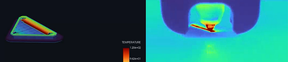
Simulation tracks the exact temperature history throughout the suppressor geometry across the heating ramp, high-temperature isothermal soak, and controlled cool-down. It predicts temperature gradients between thick outer mounting shoulders and delicate thin-walled internal baffles, pinpointing where thermal lag occurs.
2. Macroscopic Viscous Sintering & Density Evolution
Continuum sintering models calculate volumetric densification, relative density distribution, and the resulting non-linear shrinkage. By solving for the time-dependent viscous flow of the porous powder skeleton, the solver accounts for:
Contact mechanics and friction coefficients at the setter plate.
Gravity-induced slump of internal baffle structures.
Differential shrinkage driven by wall-thickness variations.
3. Cross-Sectional Diagnostic Inspection
Through interactive slicing planes and displacement scalar fields, engineers can inspect internal chambers without destructive testing. The simulation reveals whether asymmetric gas-routing ports create localized bending moments that warp the core tube away from the nominal bullet path.
4. Automated Geometry Pre-Compensation (Counter-Deformation)
Rather than printing the nominal CAD geometry and hoping it lands within tolerance after shrinkage and sag, the inverted displacement field from the simulation is applied directly to the CAD/mesh model.
The solver generates an intentionally warped "pre-compensated" green geometry.
As the pre-compensated part shrinks, sags, and drags against the setter plate in the furnace, it pulls itself directly into the nominal target tolerances.
The Value for the Manufacturer
Elimination of Furnace Scrap: Suppressor bodies that warp or banana during sintering cannot be straightened; they are immediate scrap. Simulation verifies design manufacturability before lighting the furnace.
Guaranteed Bore Alignment: Predicting and counteracting bore-line deflection ensures consistent clearance across the entire baffle stack, eliminating baffle strikes and costly post-sinter secondary bore-reaming operations.
Freedom to Design for Flow, Not Sintering: Engineers can push aggressive, asymmetric internal flow architectures knowing that gravity sag and friction pull will be systematically pre-compensated in the software stage.
Faster Time to Production: Prototype turnaround drops from months of multi-iteration sintering trials to hours of desktop solver computation.


Comments