
Printing Removable Partial Dentals in Cobalt-Chromium: How Support Structure Choice Shapes the Outcome

Laser Powder Bed Fusion (LPBF) has become a workhorse for producing removable partial denture (RPD) frameworks in cobalt-chromium. Co-Cr is the long-standing default for partial frameworks — stiff, strong, corrosion-resistant, well understood clinically, and economical — and it prints to the kind of thin, organic, lace-like geometry a partial demands without the casting headaches of the traditional workflow. But anyone who has run these builds knows the framework is only half the problem. The other half is what holds it up while it prints: the support structure.
The images in this post follow a single maxillary partial framework — the same part, the same orientation — carried through two different support strategies and then simulated for residual distortion and stress. Seeing the same geometry both ways makes the trade-offs unusually concrete. Below is a walk through what each strategy does well, where it hurts, and how the simulation results tie it all together.
Why supports are unavoidable here
In LPBF, each layer of molten metal has to solidify onto something rigid. Loose powder underneath an overhang can't resist the downward pull or the thermal contraction of the cooling melt pool. Without anchoring, downward-facing surfaces sag, curl, and in the worst case collapse into the powder bed before the build finishes. Supports exist to do three jobs at once: anchor the part to the build plate, hold up overhanging surfaces, and pull heat out of the part so it cools more evenly.
That third job matters more than people expect. The distortion you see in a finished LPBF part is mostly a thermal story. Every melt-and-cool cycle leaves the metal wanting to shrink, and the layers below resist that shrinkage. Stress accumulates layer by layer until the part is cut from the plate — at which point it springs into whatever shape balances all that locked-in strain. Supports are one of the few levers you have to steer that outcome.
Co-Cr raises the stakes in a particular way. It's a stiff, high-yield alloy — considerably more rigid than titanium — which means that for a given amount of locked-in strain it springs back less but holds more residual stress. Good news for dimensional accuracy at the clasp tips; something to respect at the fillets and finish lines, where that stored stress concentrates. The support strategy is one of the main tools for managing both.
A partial framework is an especially hard case. It is thin, it is almost entirely curved and overhanging, and it is riddled with the clasps, rests, retention lattices, and finish lines that make it clinically useful. There is very little "easy" surface. Whatever support strategy you choose, there's a lot of it, and it touches delicate features.
Strategy 1: Tree (branching) supports

The appeal is contact area. Because trees only kiss the surface at their branch tips, they leave minimal witness marks and are comparatively quick to snap or clip off. On a part with this many visible, patient-facing surfaces, that's a real advantage: less grinding, less polishing, less risk of gouging a finish line during removal. Trees also use less material and powder than solid supports, so they're economical and leave the surrounding powder easier to recover.

The cost is rigidity and heat. Thin branches are springy. They anchor the part well enough to keep it from detaching, but they don't do much to resist the slow, cumulative thermal contraction pulling on long thin spans. They're also poor heat conductors — a narrow branch is a narrow pipe for pulling warmth out of the part — so the framework runs hotter and builds up more residual strain. With Co-Cr's hardness, there's a second sting at removal: the alloy is tougher to cut and grind than titanium, so even the "easy" snap-off supports demand more finishing effort than you'd expect. On tall, isolated features this can bite: notice how the thin clasp arms in the tree-supported build end up among the highest-displacement regions once the part relaxes.
Trees are the right call when surface finish is king and the geometry is reasonably compact, but they are the weaker of the two at controlling distortion on a large, floppy framework.
Strategy 2: Lattice supports

The appeal is balance. A lattice is far stiffer and more thermally conductive than trees, because it's a connected network rather than isolated branches, yet it's hollow and perforated, so it uses far less powder than a solid wall of material would. The open cells also break up and come away more cleanly than a continuous support, and they let trapped powder drain and be recovered. For a part like this — big, thin, distortion-prone, but also finish-sensitive — a lattice holds the broad spans rigidly while keeping the Co-Cr removal labor to something manageable.
The cost is contact and tuning. All that edge-gripping contact is the price of the rigidity: there's more to grind off than with trees, and more witness area to blend back on patient-facing surfaces. A lattice also has more knobs — cell size, wall thickness, how densely it contacts the part. Get it too sparse and it behaves like weak trees and lets the part move; too dense and you're back to heavy material use and removal effort. It takes iteration, and the right settings are part- and orientation-specific.
What the simulation actually tells us
This is where the process-simulation outputs earn their place. Before committing powder and machine time, you can predict how each support scheme will leave the part — and the results sharpen the comparison above.

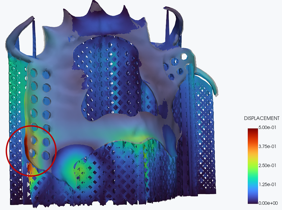
Displacement (springback). The displacement plots show how far the framework moves once it's released from the plate and the supports are removed. On this geometry the pattern is consistent: the bulk of the saddle area stays close to nominal (deep blue), while the thin, cantilevered extremities — the clasp arms and the lower border — swing the most. On the tree-supported build the worst local springback reaches roughly 0.73 mm, and the relaxed part (supports deactivated) shows the clasp tips as the hot spots, approaching and exceeding 0.7 mm of deviation. For a clinical part that has to seat passively on a model, deviations of that size at the clasp tips are exactly the ones that cause fit problems and chairside adjustment.
The lattice-supported case tells a slightly gentler story in the body of the part — peak displacement in the stiffened regions lands lower (around 0.49 mm in the simulated build) — which is consistent with a lattice's greater rigidity holding the broad spans in place better than springy trees, while still leaving the free-standing clasps as the dominant movers.

Residual stress (von Mises). The stress plots show where locked-in strain concentrates. In both support schemes the fields are similar in character — low stress across the open membrane, with the peaks clustering at the fillets and transitions: where clasps meet the major connector, around the retention-hole borders, and along the lower rim. Those are the geometric stress risers, and they're also where in-service fatigue cracks tend to start. Because Co-Cr is stiffer and higher-yield than titanium, more of the thermal mismatch stays stored as stress rather than bleeding off as movement — so these risers deserve particular attention, and stress-relief heat treatment before plate removal is standard practice for a reason. The support strategy doesn't move those hot spots so much as it changes how much the part relieves them by deforming — which is simply the stress-and-distortion trade-off restated. A stiffer support holds dimensions but leaves more strain in the metal; a springier one bleeds off strain by letting the part move.
Choosing, in practice
There is no universally correct support structure for a Co-Cr partial — only the right one for your priorities on a given case.
Lead with trees when the part is compact and surface finish and fast removal dominate, and you can tolerate more springback at thin features — remembering that even clip-off supports are more work to finish in a hard alloy.
Lead with a lattice when the framework is large, thin, and distortion-prone and dimensional accuracy matters more than minimizing bench time — accepting more contact to clean up and some tuning to dial it in.
Factor in the whole clock, not just the print. For a dental lab, the number that matters isn't powder cost — it's total turnaround and chair-ready labor. That reframes the trade-off. Trees come off fast (call it ~5 minutes of clipping and light grinding per framework) but can hand back a part that needs 20–30 minutes of fitting and adjustment to seat passively, because the thin clasps sprang out of tolerance. A lattice costs more at the bench (closer to ~15 minutes of grinding to clear all that contact) yet can erase much of that downstream adjustment by holding the framework closer to nominal. Net it out and the "slower" support is often the faster route to a seated part — which is exactly the calculation process simulation lets you run before you commit a build, not after. (Treat these minutes as illustrative; plug in your own bench times to make the comparison exact.)
The deeper point is that support choice isn't a bookkeeping step after the framework is designed. For a part this thin and this distortion-prone, it's a first-class design decision that determines whether the framework comes off the plate ready to seat or ready for an afternoon of rework. And with process simulation, it's a decision you can now make with eyes open — testing tree versus lattice in software, watching where the clasps spring and where the stress piles up, and printing only once you've found the strategy that lands the part where you need it.
The displacement and stress predictions shown here were produced on the Rheona platform — try different support strategies against your own frameworks before you commit a build. Get in touch to see it on your parts.
The framework shown is a maxillary RPD printed in cobalt-chromium, carried through tree and lattice support strategies with matched build orientation. Displacement and von Mises fields are from process simulation of the deposition sequence followed by a springback (support-removal) step.


Comments